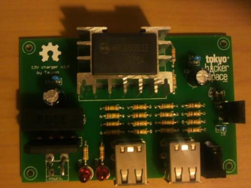
Just a couple of days after the Great Tohoku Earthquake, everybody at Tokyo HackerSpace was working on projects of their own. This is a project that began at that time but was stalled due to lots of reasons. We might be late for people of Tohoku, but the project is ready for manufacturing for other disasters around the world.
One problem we saw was that people were in these shelters without any type of communication. Sure they had cellphones but cellular system was down and charging their phones impossible as all had left their chargers at home. We couldn’t have done anything about cellular system but there was chance that we could help them charge their cellphones.
Story of v1.0
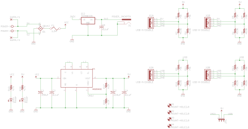
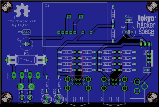
The circuit is formed around the HRD05003E 5V switch mode buck converter module. Initially we thought about soldering them up to some perfboards, wiring all the circuitry by hand and just installing a couple of phone connection cables. But it turns out that this module has a strange footprint that didn’t allow us to solder it on a perfboard. A quick board was designed but it was never produced as people working on this project with me had other immediate projects they had to. It was all through hole parts for easy soldering by newbies not so experienced people. This design had some flaws, such as USB connectors were all over the place and drilling holes for them would be a nightmare. So just a quick prototype was produced for footprint trials and everything looked good. You can see its schematic and board file below.
Kickin’ it up a notch version!
Female USB A connectors were consuming a lot of space so they were changed to stacked USB connectors. Also all connections were moved to one side of the board for easy case manufacturing. A fuse was added for protecting the converter module and another LED was added to the 12V connection side for seeing if there is a problem with power connection or fuse. You can see v2.0 schematic and board file below.
So how does it work?
Power connection is directly connected to a bridge rectifier, this ensures that nobody will worry if they plugged power correct or not in the field. Then it there is the fuse for protection. The 5V DC-DC converter module takes care of the rest. It’s output is connected to the first connector with iPhone charging capabilities. Another path is connected to a jumper where you either enable the second set of connectors (again iPhone charging capable)or you can power up a 3.3V 1A linear regulator for powering up other equipment through a 2.1mm center positive connector. This capability was included as initially we were thinking about using these for powering some wireless routers flashed with DD-Wrt. These were part of a network we were planning to set up for communication between shelters.
What about parts values?
You can see the values of components I used in the list. I couldn’t find some of the values, so I simply kept the ratio in voltage dividers and changed both resistor values. Had no problem with that.
| Part | Quantity | Value | Package |
| B1 | 1 | GBU4J | GBU4S |
| C1,C2 | 1 | 220uF | E3,5-8 |
| C3,C4,C5 | 3 | 0.1uF | C025-030X050 |
| F1 | 1 | 1.5A | FUSE 5x20mm |
| IC1 | 1 | HRD05003E | CONV-PACK |
| IC2 | 1 | TA48033S | TO220V |
| LED1,LED2 | 2 | Power | LED5MM |
| POWER | 1 | Screw terminal | W237-102 |
| R1,R3,R5,R7,R9,R11,R13,R15 | 8 | 75k | 0207/10 |
| R2,R4,R6,R8,R10,R12,R14,R16 | 8 | 49.9k | 0207/10 |
| R17,R18 | 2 | 6.2k | 0207/10 |
| R19,R20 | 2 | 4.7k | 0207/10 |
| X1,X2 | 2 | USB-A-DOUBLE | USB-A-DOUBLE |
For example, in the prototype I soldered, I used 6.8k instead of 6.2k, 150k instead of 75k and 100k instead of 49.9k.
Acknowledgements
I want to thank these people for their direct or indirect support:
MRE: For finding the module and his great ideas.
Akiba: For checking out my desing from time to time.
Torsten Wagner: For his last minute suggestions. I was not able to do them all, but I’ll include all of them in v2.1 (such as making this completely 1 sided board).
David Siren Eisner: For supplying me the v1.0 prototype board.
All the folks at THS: For their ideas, criticism and support.
LadyAda: For her tutorial about iPhone charging.
Dangerous Prototypes folks: For the ULP file I used for creating the PNG files and the partlist.
License
This project is licensed as CC-BY-SA.


I think this is a wonderful idea and I would love to buy a set of kits or boards . My brother recently just setup a solar emergency kit but the power supply we have is a very expensive Opus Solutions ATX DC-DC supply. It would be great to run a motherboard off of but it is overkill to charge some phones with. Plus the size was also an issue. Please let me know if you plan on having some for sale. Also I am going to blog about this cool project.
At THS, we are planning to turn this into a kit for a web shop we have. I’ll post about it when that happens.
Awesome news and Thank you for reaching out to those in need.
[…] emergency phone charger v2.0 – [Link] Tags: Charger, phone Filed in Power | 1 views No Comments […]
[…] Tayken gave a shout out to LadyAda for her tutorial about iPhone charging and developed cellphone charger for use in disaster situations. […]
Hi Tayken,
Any progress with making kits available?
Thanks, Brian.
Hi Brian,
We are still working on forming up a kit, but I want these units to get a field test of some sort first. So I sent one of the assembled boards with a friend to a volunteer group working up north. Once I get their feedback, the kits will be put up on THS shop. I’ll announce this in my blog.